This is part of the TechEd Section.
As mentioned previously, I was on the look out for a suitable Solar sensor to provide measurement of the strength of the Sunlight on our property. Now where the RG-11 is located is actually quite an ideal place for determining Solar light levels, as it has a clear view to sky all round. Then I got thinking, what if I put the solar sensor ‘in’ the RG-11 housing itself, given its completely transparent at the top, it gets plenty of Sunlight in there.
So I had a look around Jaycar and found a suitable Light Dependent Resistor, the intention being to make use of the one ‘free’ cable core from the RG-11 to the Arduino. With the LDR being wired to ground and on the other side returned down the cable core. On the Arduino side, would be a simple resistor divider using a 4.8k resistor to 5v, the LDR output then fed into A0 on the Arduino.
What I did was get some very fine cables and wired up the LDR to them, using heat shrink tubing over the solder join to ensure it would not short to anything on the front of the RG-11 PCB. This turned out to be quite a good idea..
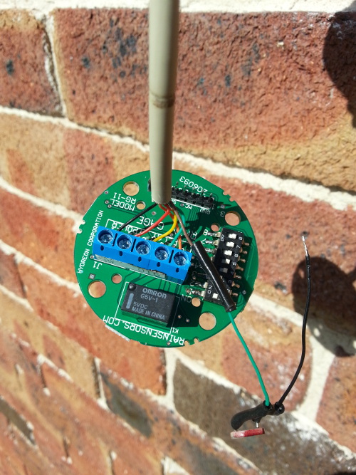 As you can see on the picture on the right, the LDR is wired to the Green wire going back to the Arduino, and the black wire I will screw into the left hand screw terminal on J1 connector, the black cable goes to Ground at the other end.
Installation was a little tricky, but I found the fact I had shrink wrapped the wire came in useful as there was a transistor can just in the right place on the other side to ‘pin’ the transistor between the wires and thereby hold the LDR in place as the RG-11 was reassembled.
Once reassembled you would not know the RG-11 was doing a double function now, measuring both rainfall and solar.
Arduino side…
As for Arduino programming, what I decided to do was set up a decaying average with an Alpha of 0.05, i.e. decays over 20 reads. With one read per second. This way a bird, plane or other short term shadow was not going to produce a bad reading. This was easy to implement as I had a routine that was being called 20 times a second, with a counter built in to run a condition once a second. The code is shown below.
solarAverage = (SOLAR_ALPHA * analogRead(SOLAR)) + ((1.0-SOLAR_ALPHA)*solarAverage);
So solarAverage (float) is the current averaged value, and the SOLAR_ALPHA (constant) is the alpha value mentioned above.
BTW This is so much easier than how coding of micro-controllers used to be only a few years ago, then it was a mix of assembly and custom C code, combined with an in depth low level awareness of the capabilities of the controller in question.
This is now been fed into the database after being subtracted from 1023, this way the value increased with brightness, which makes more sense to mortal man.
Uses..
Well the first use has been to tie into the Home Automation system to allow the system to know when it is actually dark, rather than just trying to calculate it based on solar orbits.. This means if we get a very cloudy day, the lights indoor will kick in, when they didn’t before.
The next use will be to get a graph generated for it. I think we have enough sensor readings to make a proper house weather dashboard now.
Next..
A Barometric Sensor is on order, this should be easy to interface in…