This is part of the TechEd Section.
My project of tying together various sensors to work out what is happening around the property is taking shape.
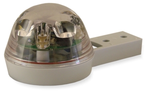 I just took delivery of the Hydreon RG-11 Optical Rain Sensor a few days ago, cost $99 plus postage from Ocean Controls. A nifty little unit that makes use of the same technology as rain sensors on car windscreens to detect rain.
It works from either 12v DC or AC and provides a NO/NC relay output that is voltage free – i.e. you can hook up your own circuit on the output side. It has various modes of operation to allow it be used as a simple tipping bucket replacement right up to automatic control of awnings if needed and ‘rain delay’ type processing.
What I liked about it was:
- It’s a small self contained sensor with no moving parts or things to become ‘blocked’, given I live on a block with lots of trees, dust, insects, birds, bird droppings, etc – anything that actually collects rain water will collect a lot of other things as well over time and just fail.
- Simple to set up and easy to tell if is operating correctly (as a green LED flashes when it detects rain; much fun was had by my two boys tipping water on the sensor from the deck to get the LED to flash…).
RG-11 Installation
I decided to mount the sensor on a bracket from Bunnings that put it about 40cm off the wall by the deck and well away from any over hangs. I know this might give us an indication of slightly more rain than there actually is, due to rain bouncing off the deck onto the sensor, but I consider that a very minor point and not that likely to be significant – also it will take rather a lot of rain for that to happen.
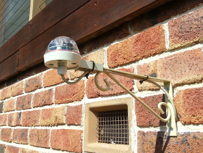
The bracket I painted twice and then sealed with clear spray on – I know how things quickly degrade outside in Australia if you don’t go out of your way to protect beyond the thin layer of spray paint they come with – this also gave me the chance to match the colour scheme for house fittings. The bracket will also double up to support a hanging basket, so everyone is happy!
I decided to make use of a 6 way cable, so I could wire up all the 5 connectors to the sensor (2 supply, 3 relay) and then decide with ease how to wire it in at the Arduino.
RG-11 Installation Tips
- Install the cable from the Arduino to the sensor and feed it through the tightening nut and the grommet, do not try going the other way! Doing it this way guarantees everything is where it should be and that you have enough cable…
- Avoid trying to assemble the RG-11 right way up, you will drive yourself nuts trying to get the little rubber ring to sit on its shelf on the base. Instead turn it upside down, put the ring in its grove in the clear top and assemble upside down ‘off’ its final attachment point; then put the whole completed unit in place.
- Also strip slightly more cable than you think and double back the exposed wire into the connectors – this will ensure a good grip on the wire – finish off with a little wrap of electrical tape around the cable, this way if you do happen to pull on the cable when finally assembled – it won’t pull it out of the connectors.
- Use cable ties to hold the cable under the bracket and leave a nice little ‘loop’ under the sensor, so the rain has no way to go ‘up’ into the sensor housing, its also shades the cable from the punishing Australian Sun – UV stabilized or not the Sun here just fries cables…
Arduino Wiring in of the Rain Sensor
This was actually quite simple, the common on the relay was wired to ground (0v) and the NO (normally open side) was wired to a 10k resistor to 5v and a 100 ohm resistor to a digital input pin on the Arduino.
Arduino Software Interfacing…
Now, given I had the 2 interrupt pins in use for the RS485 – I need to a way to check the rain sensor without interrupts. The technique I can up with made use of the fact I was already using the MsTimer2 library to do timed operation of relays for the irrigation. I know the RG-11 will produce a 50ms pulse (says so in the docs), so I just need to query the digital input pin for LOW state 20 times a second, this I did by changing the MsTimer2 to call its ‘kick’ function every 50ms and then scaled the per second routine inside to use a count down from 20 to ensure that only ran once a second.
This little ‘hack’ worked a treat.
I actually coded it up so that I now have the following additional functionality:
- Remote reading of the current ‘count’ with the option to reset (this gets used to update a Database every 10 minutes).
- Remote reading of separate decay ‘count’ with the option to reset (this goes up to a maximum, where as the other counter does not).
- Setting a persistent flag (in EEPROM) to enable ‘rain Delay’ functionality.
- Setting a rainDecay value (option to set in EEPROM) that gets knocked off the decay count per hour – this with a master ‘inhibit irrigation’ relay means I can stop watering when I know the ground is wet.
- This state is then preserved if I wish to do a priority timed watering (i.e. I specifically instruct I want to water regardless of the rain Delay counter state).
Conclusion
Installation and usage of the RG-11 was actually a lot easier than I expected; I now have a rain detection system with 0.01mm resolution that records to a Database AND does its own smarts on Rain delay with custom override support.
Additional Tweaks/To do List
- Recording in the Database the value of the decay count – I get that reported back.
- Get my eldest son to extend the graphing to cover the rain and decay counts.
- Integration with the BOM weather feed – so I can delay in advance of predicted rain events (using the timed ‘inhibit irrigation’ relay).
- A proper daylight sensor – been looking around on the Net, nothing yet seems quite right.